Why Multi-Driver IEMs Sound Blurry: Phase Alignment Physics in Hybrid Acoustics

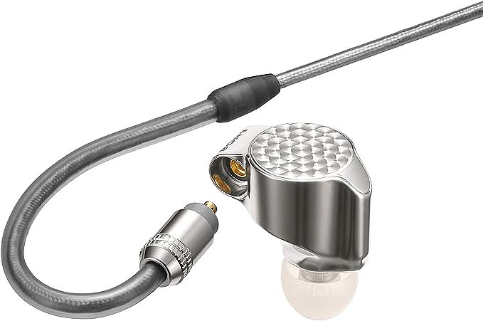
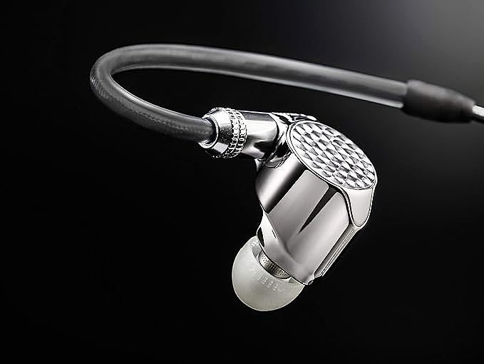
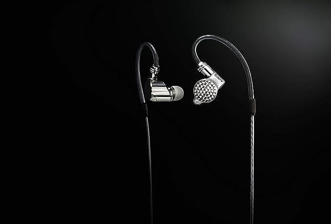
Sony IER-Z1R Signature Series in-Ear Headphones
Listen closely to a busy orchestral passage through a multi-driver in-ear monitor and you will notice that strings and brass collapse into a single wall of sound while cymbal attacks lose their edges and the spatial separation between instruments vanishes. The problem is not your source file or your amplifier, but rather lives inside the acoustic cavity pressed against your eardrum where sound waves from multiple drivers arrive at slightly different times and tear each other apart through destructive interference.
This is the phase alignment problem, the central engineering challenge in any hybrid multi-driver in-ear monitor. When engineers designed the IER-Z1R, they attacked this problem not with digital signal processing but with physical geometry, revealing something fundamental about acoustic engineering: sometimes the cleanest solution is structural, not electrical.
Two Waves Walk Into an Ear Canal
Phase interference is not abstract physics but rather the reason some frequencies in your music sound hollow while others sound bloated. When two sound waves carrying the same frequency arrive at your eardrum at different times, their pressure fronts interact such that if the peaks align they reinforce each other while if a peak meets a trough they cancel. In a multi-driver in-ear monitor, this happens at every crossover frequency where two drivers share the same band.
Consider what actually occurs inside the cavity where a 5mm tweeter sits closer to the ear canal entrance, a 12mm mid-bass driver sits a few millimeters behind it, and a sub-bass driver sits deeper still. Sound travels at approximately 343 meters per second in air at room temperature. Inside an IEM cavity, the propagation distance from each driver to the eardrum spans roughly 10 to 20 millimeters. That translates to a travel time of roughly 0.03 to 0.06 milliseconds.
That fraction of a millisecond is enough to wreck phase coherence at crossover frequencies. At 2,000 Hz, a single wavelength lasts 0.5 milliseconds. A time misalignment of 0.25 milliseconds shifts the phase by 180 degrees, meaning the two drivers annihilate each other at that frequency instead of reinforcing. The listener perceives a notch, a dip, a hole in the frequency response that no equalizer can fix without introducing new problems elsewhere.
Traditional multi-driver IEMs address this with passive crossover networks: capacitors and inductors that split the frequency range and route each band to the appropriate driver. These components handle frequency division adequately. They do not handle phase alignment. A capacitor introduces a phase shift of its own. An inductor introduces another. The cumulative phase error at crossover points becomes an unavoidable byproduct of the circuit topology.
Geometry as Signal Processing
The Refined-phase structure takes a different path. Instead of correcting phase errors electrically after they occur, it prevents them from occurring in the first place by controlling the physical acoustic path from each driver to the ear canal entrance.
The inner housing is machined from magnesium alloy, not merely for cosmetic reasons but for its acoustic properties. Magnesium has a density of approximately 1.74 grams per cubic centimeter, roughly two-thirds that of aluminum, combined with an elastic modulus around 45 GPa, giving it a high stiffness-to-weight ratio which means the cavity walls resist deformation under acoustic pressure while adding minimal mass to the assembly.
More critically, magnesium exhibits superior internal damping compared to aluminum. When sound waves strike the cavity walls, the material absorbs energy rather than reflecting it back into the acoustic space, reducing the standing wave patterns that contribute to phase distortion.
Inside this magnesium shell, the geometry is deliberately irregular. A perfectly cylindrical or rectangular cavity creates predictable standing wave modes where specific frequencies resonate at specific distances between parallel surfaces, but by breaking the symmetry of the internal geometry, the Refined-phase structure disperses these standing wave frequencies across multiple non-harmonically-related values so that no single frequency receives a concentrated resonance spike.
The result is a smoother phase response across the entire audible band.
The positioning of each driver within this cavity follows from time-of-flight calculations. The tweeter occupies the forward-most position, approximately 10 millimeters from the sound outlet, while the mid-bass driver sits about 15 millimeters back and the sub-bass driver sits roughly 20 millimeters from the outlet.
By staggering the physical positions in proportion to the group delay characteristics of each driver type, the acoustic path lengths compensate for the inherent timing differences between driver technologies so that the sound from all three units arrives at the ear canal entrance within a sub-millisecond window.
The Rear Chamber Problem
Low frequency reproduction in sealed in-ear monitors presents a distinct set of physics challenges because the rear cavity behind a driver acts as a spring. The air trapped inside resists compression and this resistance increases as frequency drops, eventually acting as a high-pass filter that rolls off the bass response. Traditional solutions involve either venting the rear cavity, which sacrifices isolation, or accepting the bass roll-off as a design compromise.
Sound Space Control addresses this through what is essentially a pressure management system for the rear chamber where the rear cavity volume is precisely matched to the driver parameters, specifically the compliance of the suspension and the effective radiating area.
This matching determines the resonant frequency of the sealed system and, consequently, the low-frequency cutoff slope.
The geometry of the rear cavity also matters because in a simple enclosed volume, standing waves form at frequencies determined by the cavity dimensions. For a cavity roughly 15 millimeters in its longest dimension, the first standing wave mode occurs around 5.7 kHz, calculated from the quarter-wavelength resonance formula, squarely in the sensitive mid-treble region.
Sound Space Control employs an irregular cavity shape that prevents the formation of a coherent plane wave front inside the rear chamber, and without coherent reflection surfaces, standing waves cannot establish stable patterns at predictable frequencies, meaning the energy that would concentrate at a single resonant frequency spreads across a broader range, reducing the amplitude of any individual resonance peak to below audibility.
This approach preserves the sealed design, maintaining isolation from external noise, while achieving a low-frequency extension that approaches what vented designs can offer. The trade-off is manufacturing complexity. An irregular cavity with specific volume constraints and precisely positioned internal features requires tight dimensional control during production.
When Three Drivers Become One
The crossover design in a triple-driver hybrid system must solve two simultaneous problems: frequency division and phase coherence. Each problem constrains the other. You cannot freely choose crossover frequencies without considering the phase relationship at the boundaries. You cannot optimize phase at the crossover without constraining the filter topology, which in turn affects the slope and bandwidth of the frequency division.
In this system, the crossover points are estimated to fall near 500 to 800 Hz between the mid-bass and sub-bass units, and near 2 to 3 kHz between the tweeter and mid-bass units. At each of these boundaries, both adjacent drivers contribute to the output. The sum of their outputs must approximate a flat magnitude response and a smooth phase response. Any deviation in either domain creates an audible artifact: a peak, a dip, or a smear in the time domain.
The physical positioning strategy works in concert with acoustic filtering. Acoustic filters, implemented as tuned tubes and chambers within the cavity, provide frequency-dependent attenuation and delay that complements the driver positioning. Where the physical distance cannot fully compensate for a group delay difference, the acoustic filter adds the remaining time correction. This dual approach, structural alignment supplemented by acoustic filtering, achieves tighter phase coherence than either method alone.
The manufacturing tolerances tell the story of how precise this alignment must be. Critical dimensions are held to within 0.05 millimeters. The cavity machining tolerance reaches 0.01 millimeters. At these scales, a shift of one-tenth of a millimeter in driver position alters the arrival time by approximately 0.3 microseconds. While this seems negligible, cumulative errors across multiple dimensions compound. The hand-assembly process at the manufacturer's Sun Factory, the same facility that produces broadcast-grade microphones and studio reference monitors, exists precisely because automated assembly cannot yet achieve the micro-adjustments that experienced technicians perform during final acoustic tuning.
Frequencies You Cannot Hear Still Matter
The specification listing a frequency response reaching 100 kHz invites skepticism because human hearing tops out around 20 kHz, and even that upper limit applies only to young, healthy ears while most adults perceive nothing above 15 to 16 kHz, making it seem that engineering a transducer to reproduce frequencies five times beyond the audible ceiling is, at first glance, like a solution searching for a problem.
The reasoning becomes clear when you stop thinking about frequencies and start thinking about time.
A transducer's bandwidth and its transient response are linked through frequency analysis because the rise time of a system, the speed at which it can respond to a sudden change in the input signal, is inversely proportional to its bandwidth. A system with a 20 kHz bandwidth has a theoretical minimum rise time of approximately 17.5 microseconds, but extend that bandwidth to 100 kHz and the theoretical minimum drops to about 3.5 microseconds. This means the system can track faster changes in the waveform.
This matters because music is full of fast changes like the attack of a snare drum, the initial transient of a plucked string, and the percussive consonants in vocal performance. These events contain energy spread across a wide frequency range including components above 20 kHz, and when a transducer cannot reproduce those ultra-high-frequency components, the time-domain representation of the transient is smeared. The attack loses sharpness and the decay loses definition.
There is also the matter of phase linearity because for a minimum-phase system, which describes most passive acoustic transducers, the magnitude response and the phase response are mathematically connected. A smooth magnitude response produces a smooth phase response while an abrupt roll-off in magnitude produces an abrupt deviation in phase. When a driver's response drops steeply near its upper limit, the phase distortion extends below that limit into the audible range, but by extending the usable response well beyond 20 kHz, the phase response remains linear through the entire audible band. The magnitude roll-off, when it eventually occurs, happens at frequencies where it no longer affects the audible spectrum's phase integrity.
Musical harmonics provide the final justification as a piano's A4 note at 440 Hz generates harmonics at 880, 1320, 1760 Hz, and onward. By the twentieth harmonic you are at 8.8 kHz, and by the fiftieth you are at 22 kHz, already beyond the nominal hearing limit. These ultra-high harmonics contribute to the timbral signature that distinguishes a Steinway from a Bosendorfer, and a transducer that preserves the natural decay of these harmonics maintains more of the original instrument's character.
Ear Canals Are Not Cylinders
Acoustic engineering does not stop at the driver and cavity because the ear canal itself is part of the acoustic system. Shaped roughly like a tapered tube approximately 25 to 30 millimeters long, it presents a load that varies with frequency and differs from person to person, meaning an IEM that sounds neutral in one ear canal may sound bright or dark in another.
Decades of ear canal geometry measurements inform the housing shape. The cavity exterior is designed to match the statistical distribution of ear canal and concha shapes found across a large population sample, while the sound outlet position and angle are specified to optimize the acoustic coupling between the driver assembly and the ear canal entrance.
This is population-level ergonomics: not a custom fit for one individual, but an optimized compromise for the statistical majority.
The over-ear cable routing serves an acoustic purpose beyond cable management because by securing the cable over the top of the ear, the IEM body maintains consistent positioning relative to the ear canal. This positional stability ensures that the acoustic coupling remains constant during movement while also reducing the mechanical vibration transmitted through the cable to the ear canal, a phenomenon known as microphony or the stethoscope effect. Cable-induced vibrations enter the ear canal as low-frequency noise, masking the sub-bass frequencies that the Sound Space Control system was designed to reproduce cleanly.
The Shape of Sound Before It Becomes Sound
There is a quiet principle at work in all of this: the most sophisticated signal processing in a multi-driver in-ear monitor happens before the amplifier, before the crossover, before the signal reaches the drivers at all. It happens in the physical dimensions of a cavity, the placement of a baffle, and the curvature of an internal wall. Phase alignment achieved through geometry does not degrade with component aging, does not vary with temperature, and does not introduce noise floor or distortion artifacts. It simply is, fixed in magnesium and air, every time you put the monitor in your ear.
The constraint is that this approach demands precision that borders on the absurd: machining tolerances measured in hundredths of a millimeter, assembly adjustments performed by hand by technicians who have spent years developing a feel for acoustic alignment, and quality control measurements that verify each unit against a target curve within plus or minus two decibels. This is why structural phase alignment remains rare in consumer audio: not because the physics is unknown, but because the manufacturing discipline required to implement it consistently is prohibitively expensive for most product categories.
The next time you listen to a well-recorded track through a multi-driver IEM and hear clean separation between instruments in a dense passage, consider that what you are hearing is not just driver quality or amplifier power. What you are hearing is the absence of destruction: sound waves that arrived at your eardrum without canceling each other, transients preserved because the phase response stayed linear, and bass that extended cleanly because standing waves never formed. In acoustic engineering, the highest achievement is often not what you add to the signal, but what you prevent from taking it away.
Sony IER-Z1R Signature Series in-Ear Headphones
Related Essays

SIVGA SW001 High-Definition Wooden Wired in-Ear Monitor Earphones: A Wooden Wonder for Audiophiles

Water Sounds for Sleep: The Science Behind Nature Sounds and Neural Relaxation

Hybrid Driver Architecture: The Physics Behind Modern IEM Sound

Hybrid Driver IEM Amplifier Pairing: Impedance Matching and the 1/8 Rule

Miniaturization and Acoustic Engineering: How 6mm Drivers Produce Full-Range Sound

The Physics of Silence: Decoding 30dB Reduction and Acoustic Sealing

Beryllium Diaphragm Physics: How Stiffness-to-Weight Ratio Defines Transient Response in IEMs
Water Sounds for Sleep: The Science Behind Nature Sounds and Neural Relaxation

Wood Acoustics and Analog Signal Paths: The Physics Behind Natural Sound